
Image-Guided Calcium Modification: IVL
Can you discuss the importance of image-guided plaque assessment and the use of plaque modification techniques?
Unfortunately, angiography is insensitive for detecting and quantifying arterial calcium that needs advanced vessel preparation. For that reason, we previously had a hard time teaching physicians when to utilize plaque modification, because, at least in the older era, there wasn’t a lot of information about what constitutes a lesion that needs aggressive plaque preparation.
Recently, we have evolved to rely heavily on an intravascular imaging-based approach to deal with calcified lesions; our center images over 85% of all percutaneous coronary intervention (PCI) cases. We typically apply an image-based strategy to determine the optimal stenting plan and routinely employ an algorithm called MLD MAX, (Morphology, Length, Diameter, Medial dissection, Apposition, eXpansion) which is a prescriptive way to use optical coherence tomography (OCT) or intravascular ultrasound (IVUS) to guide PCI.1 “MLD” is for the planning part of the case: define the Morphology, determine the Length of the stent, and then figure out the Diameter based on intravascular imaging. MLD encourages the assessment of calcium presence or absence, and, if present, to decide, based on the calcium morphology, whether advanced vessel preparation is needed, and then what the best vessel preparation strategy should be. The Cardiovascular Research Foundation group came out with a paper2 a few years ago demonstrating that an OCT scoring system called the calcium volume index (CVI) predicts stent expansion, and many of us have adopted this scoring system to determine when to employ plaque modification. Depending upon the arc of calcium, thickness, and calcium length, a CVI score of 3 or 4 means that if you don’t employ some degree of advanced plaque modification, stent under-expansion is far more likely to occur. Adequate stent expansion is considered 80% or greater, or optimally, 90%. There has also been a similar calcium scoring system proposed for IVUS.3 Now, when we take an image-guided approach to understanding lesion morphology, we can use an index score to evaluate the lesion to help us make decisions about plaque modification. When I image a lesion to determine whether to modify it, I will use one of the scoring systems, because I know that if I see a certain signature of calcium on IVUS or OCT, I could have trouble with stent expansion. This is especially true for long segments of thick, circumferential calcium. Interestingly, calcific nodules are one of the entities that get you a point in the IVUS scoring system, as nodular calcium impedes stent expansion and geometry. We know that when stents are not well expanded, they tend to fail.
Can you tell us more about the MLD MAX algorithm?
One of the struggles in growing adoption of intravascular imaging to guide PCI procedures was that there really were no well-practiced or well-taught ways to do so. Everybody used intravascular imaging a little bit differently; there was no consensus. To provide a prescriptive, step-by-step method to perform image-guided PCI, a group of us got together and came up with the acronym MLD MAX to plan the case and optimize the stenting result. In the pre-PCI planning phase, MLD, M stands for morphology, where the morphology we really care about is whether there is enough calcium to warrant advanced vessel preparation. In cases with substantial calcium burden, CVI ≥3, we use Shockwave, rotational atherectomy, or orbital atherectomy. We also look for any thin-capped fibroatheromas, because we know if we land stents in those areas, we can have edge dissections. The L in “MLD” stands for length, which is a surrogate for finding ‘normal to normal’, because if we leave inlet and outlet disease at the edge of the stent, the stent fails more often. The D in “MLD” stands for diameter. We use the OCT to pick the diameter of the stent based on the distal reference segment, because we know that using OCT or IVUS to determine stent sizing is far more accurate than using the angiogram, where we tend to get the sizing wrong. You drop an OCT catheter down the artery, follow the MLD steps, and your procedure planning is easy and quick. For the second part of the algorithm, MAX, the M stands for medial dissection. If you have a major medial dissection, especially at the distal stent edge, it is a problem and needs to be covered with an additional stent. The A is apposition. You look to see whether the stent is reasonably apposed. The X is expansion. You want to have the stent be 90% expanded in the minimal stent area relative to the reference segment area, although it is acceptable to be at 80%. The MLD MAX algorithm is based on data as to what matters for PCI durability, and is a simple roadmap on to how to do an image-planned and optimized PCI. As a result, procedure success and durability is left less to chance than it used to be. There are clear, randomized trial results that demonstrate intravascular imaging cuts stent failure in half and meta-analyses suggest intravascular imaging reduces PCI mortality.3-6
What has been your experience with coronary intravascular lithotripsy (IVL) across calcium morphologies?
We have been using IVL in the coronary arteries since its approval last year and have had a very pleasant experience. IVL’s ability to change the compliance of calcified lesions has been very helpful. We really like the ability to use IVL in large arteries, where previously we would have used a 2 mm Rotaburr (Boston Scientific) or several passes of orbital atherectomy at high speed. We have found significant value in adding IVL to our toolbox, including for large arteries, for extremely thick rinds of calcium upward of 0.8 mm or more, and in bifurcations, where it is nice to be able to keep wires down both branches during plaque modification. We also often utilize IVL in patients with diminished left ventricular function. In these patients, mechanical atherectomy can cause substantial stress when drilling out calcium, as particles shower downstream and adversely impact myocardial perfusion. We take great care in mechanical atherectomy cases to lessen the stress to the heart and decrease the chances of having no reflow from distal particle embolization. We often find that with a low ejection fraction patient on Impella (Abiomed), the more rotational or orbital atherectomy runs you do, and the longer the runs are, the longer it takes for the patient to recover from that run in terms of the hemodynamic parameters. For super-sick patients that need calcium modification, if you can deliver a Shockwave balloon, it is an easy and gentle way to achieve plaque modification with less risk of debris showering.
What about specific calcium morphologies such as nodular calcium?
Like all calcium, nodular is associated with worse outcomes and we know it deforms stents. If you don’t debulk it or address it, nodular calcium will leave you with a stent that is less expanded than it should be; it can be an important contributor to under-expansion. If you don’t do something to modify nodular calcium up front, you can end up beating up on it with a high-pressure noncompliant balloon after stenting, where it may be more prone to creating perforation as you drive the nodule through the vessel wall in trying for better expansion.
Prior to IVL, how were you treating nodular calcium?
We would use mechanical atherectomy, typically favoring orbital atherectomy over rotational atherectomy. The data that Akiko Maehara presented at TCT 2021 from the Disrupt CAD Pooled OCT substudy7,8 tracked more efficacy for IVL for nodular calcium than was previously supposed. This was a single-arm study and thus not randomized, and it used OCT to look at the ability of stents to have a favorable geometry and expansion when stenting a nodular lesion that had been treated with Shockwave IVL. Surprisingly, the stents and the outcomes looked good with IVL compared to what we know about ballooning nodular calcium and putting in a stent, where we see stents with suboptimal geometry and suboptimal expansion. Our own anecdotal experience had been that IVL worked better than anticipated in nodular calcium, so it was nice to see that the data supported value for IVL technology in this difficult-to-treat entity.
Do you have any best practices to share?
Best practices are to use intravascular imaging to guide PCI procedures. Knowing which atherectomy device to choose can be influenced by your pre imaging. If it is nodular calcium, you may choose differently than if it is a small artery with concentric calcium. Image-guided plaque modification requires the ability to deliver an imaging catheter. If you can only get a wire across and nothing else, then it is obviously going to be a rotational or an orbital atherectomy case. The algorithms for image-guided calcium treatment and modification focus on the crux point of whether a device can get through. There is no harm to doing rotational or orbital atherectomy, or ballooning, in order to get your OCT catheter down and figure out what is going on. We often talk about calcium fracture as a marker of change in vessel compliance, as a sign that it is now feasible to stent. If you are uncertain about whether you have achieved adequate lesion preparation, at least when you are using orbital and rotational atherectomy, looking for a fracture of the calcium after ballooning informs whether you achieved a change in the compliance that will enable your stent to expand well. There is a caveat to that, however. Our thinking on whether you need to see calcium fracture to stent is being revisited with IVL technology, because it works differently than mechanical atherectomy devices. The Disrupt CAD III trial had an OCT substudy evaluating the presence of calcium fracture after treatment with the Shockwave IVL.9 They found that cases using Shockwave where calcium fracture was not visible with OCT achieved similar stent expansion to cases when calcium fracture was visible with OCT. Micro computed tomography data show that IVL-induced calcium fractures are small in size and may be below the detection limits of OCT and IVUS. Although the idea of looking for visible calcium fracture prior to stenting applies for rotational and orbital atherectomy, the calcium fractures that Shockwave IVL creates can be smaller than what can be seen with OCT. Disrupt CAD III data suggest that if calcium fractures are not visible after IVL, but your balloon expands, stents should expand well. I believe that the best practice after atherectomy or IVL is to take a one-to-one size pre-dilation balloon and look for it to expand adequately. If the balloon expands, it is reasonable to move forward with stenting. In some cases, I will perform pre PCI intracoronary imaging, plaque modify, use Shockwave IVL or orbital or rotational atherectomy, balloon, check with OCT or IVUS again to make sure calcium fracture is visible, and then stent. After post dilation, intravascular imaging assessment allows you to make sure the stent is optimized. Intravascular imaging offers a clear reality check on the fidelity of your decision-making to get to the MAX in the MLD MAX algorithm. Do I have dissections? What does my apposition look like? And do I have 90% expansion?
Any final thoughts?
People should not skip upfront planning with intravascular imaging. There is a huge difference between an image-endorsed PCI (saw the angiogram, put my balloon up, stented, and checked it on the back end with imaging) versus an image-planned PCI. An image-planned PCI involves putting the imaging catheter down, assessing the MLD portion, rationally stenting, post dilating, and checking with intravascular imaging for the MAX portion on the back end. We have done multicenter research in a program called LightLab, looking at OCT workflows1, and have found that if you do the case based on the angiogram and check the stent with OCT when you are done, you use more contrast, ironically, than planning and optimizing the case with the MLD MAX workflow. Research shows that by planning the case with imaging upfront, you save time, probably use fewer stents, and can use less contrast.
References
1. Dr. Kevin Croce: Impact of workflow on reducing procedural variability and addressing misperceptions of OCT from the LightLab Study. From: Keeping it simple: OCT workflow and AI. An Abbott-sponsored symposium at TCT 2021. Accessed January 21, 2022. Available online at https://vascular.abbott.com/abbott-at-tct.html
2. Fujino A, Mintz GS, Matsumura M, et al. A new optical coherence tomography-based calcium scoring system to predict stent underexpansion. EuroIntervention. 2018 Apr 6; 13(18): e2182-e2189. doi: 10.4244/EIJ-D-17-00962
3. Neleman T, Liu S, Tovar Forero MN, et al. The prognostic value of a validated and automated intravascular ultrasound-derived calcium score. J Cardiovasc Transl Res. 2021 Oct; 14(5): 992-1000. doi: 10.1007/s12265-021-10103-1
4. Hong SJ, Kim BK, Shin DH, et al; IVUS-XPL Investigators. Effect of intravascular ultrasound-guided vs angiography-guided everolimus-eluting stent implantation: the IVUS-XPL randomized clinical trial. JAMA. 2015 Nov 24; 314(20): 2155-2163. doi: 10.1001/jama.2015.15454. Erratum in: JAMA. 2016 Feb 2;315(5):518.
5. Zhang J, Gao X, Kan J, et al. Intravascular ultrasound versus angiography-guided drug-eluting stent implantation: the ULTIMATE trial. J Am Coll Cardiol. 2018 Dec 18; 72(24): 3126-3137. doi: 10.1016/j.jacc.2018.09.013
6. Darmoch F, Alraies MC, Al-Khadra Y, et al. Intravascular ultrasound imaging-guided versus coronary angiography-guided percutaneous coronary intervention: a systematic review and meta-analysis. J Am Heart Assoc. 2020 Mar 3; 9(5): e013678. doi: 10.1161/JAHA.119.013678
7. Ali Z, Hill J, Saito S, et al. TCT-163 Optical coherence tomography characterization of eccentric versus concentric calcium treated with Shockwave intravascular lithotripsy: patient-level pooled analysis of the Disrupt CAD OCT substudies. J Am Coll Cardiol. 2021 Nov, 78 (19_Supplement_S) B67-B68.
8. Coronary intravascular lithotripsy (IVL): research roundup at TCT with Drs. Dean Kereiakes, Ziad Ali, Akiko Maehara, and Yasin Hussain. Cath Lab Digest. 2021; 29(12): 1, 18-21. Accessed January 21, 2022. Available online at https://www.hmpgloballearningnetwork.com/site/cathlab/calcium-corner/coronary-intravascular-lithotripsy-ivl-research-roundup-tct-drs-dean
9. Hill JM, Kereiakes DJ, Shlofmitz RA, et al; Disrupt CAD III Investigators. Intravascular lithotripsy for treatment of severely calcified coronary artery disease. J Am Coll Cardiol. 2020 Dec 1; 76(22): 2635-2646. doi: 10.1016/j.jacc.2020.09.603
---
CASE REPORT
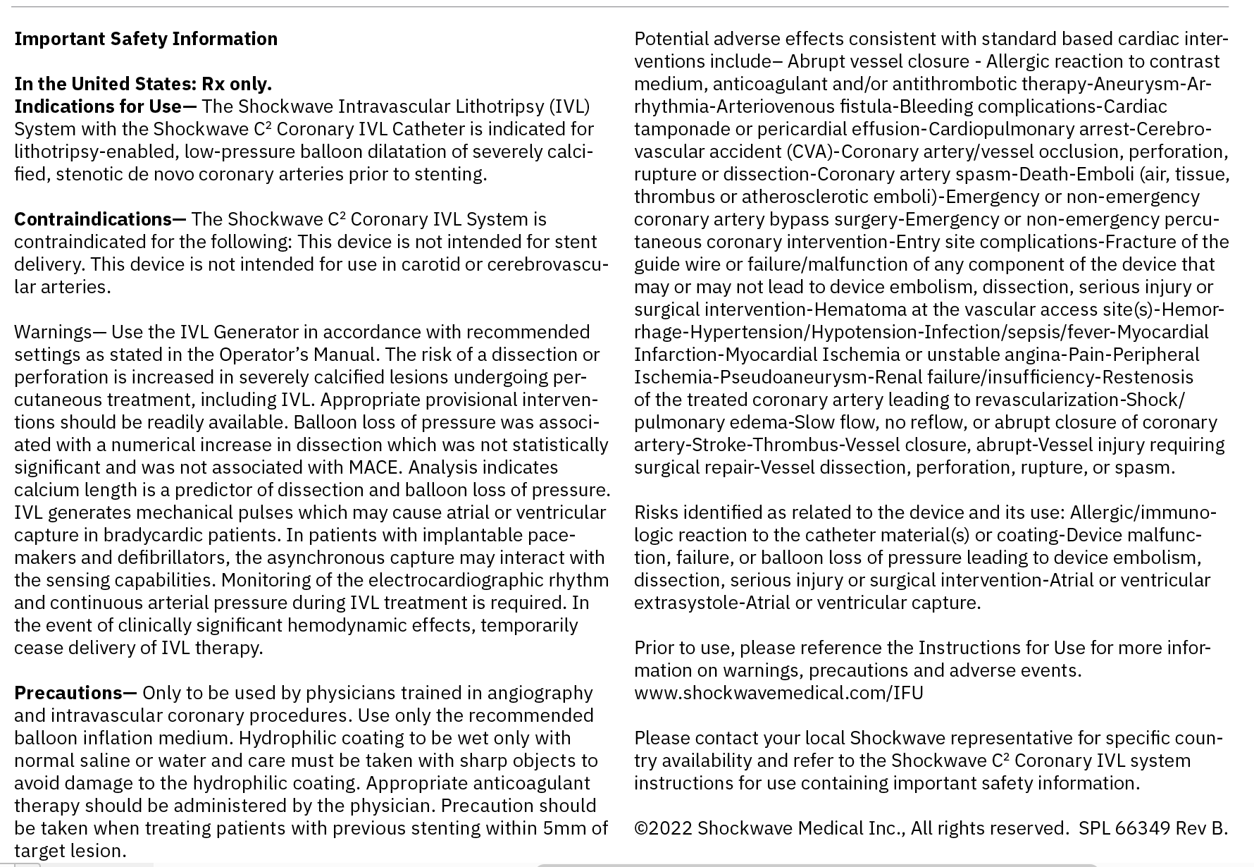
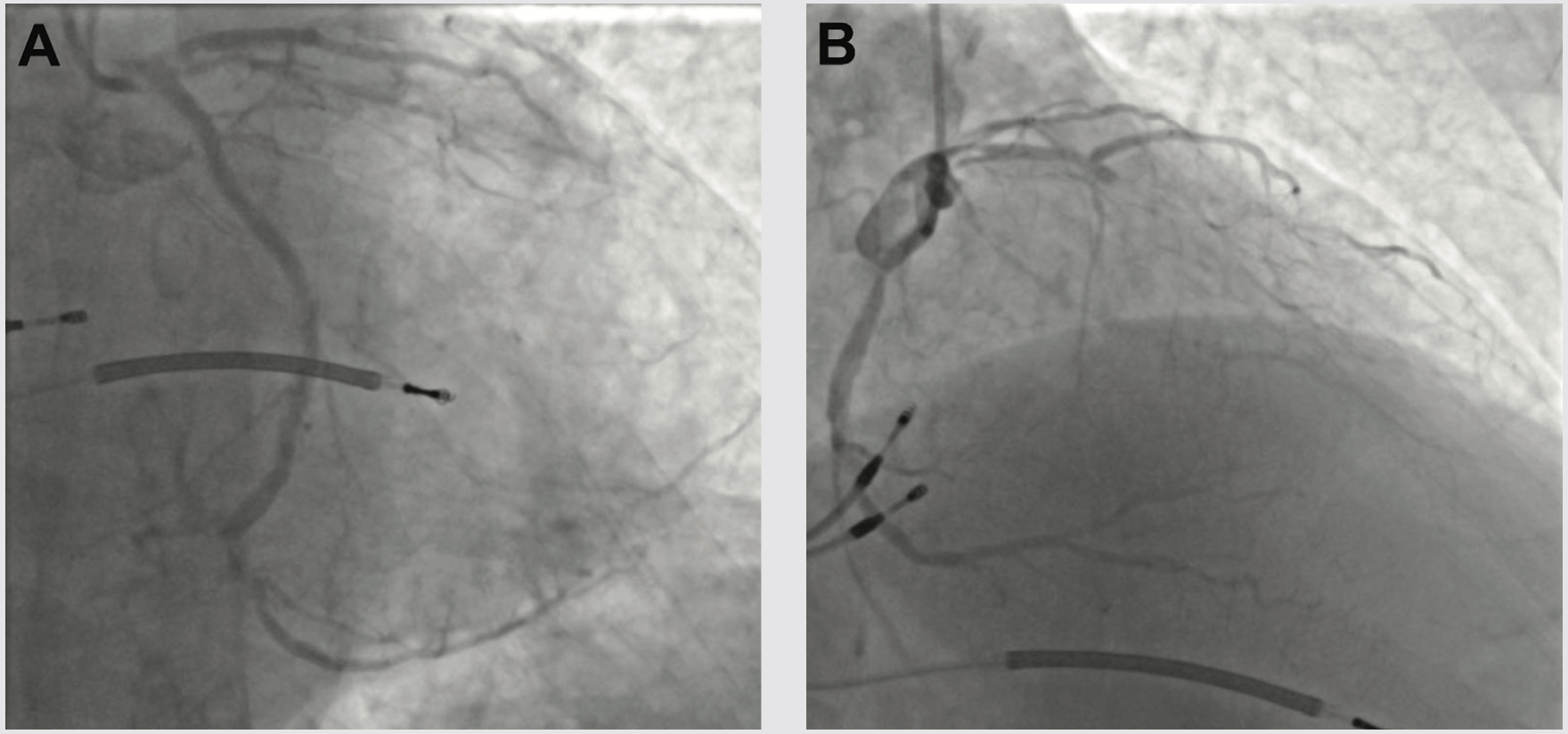
A 73-year-old male with a past medical history of coronary artery disease (CAD) and recent onset congestive heart failure on optimal medical therapy presented with Canadian class 3/4 angina for consideration of revascularization. The patient had a history of peripheral artery disease with a right iliac stent and right common femoral artery endarterectomy with patch repair. He also had a new ischemic cardiomyopathy with a left ventricular ejection fraction (LVEF) of 25%. Complete blood count was within normal limits and the creatinine was 1.2 mg/dL. Diagnostic angiography done 2 months prior demonstrated left-dominant anatomy with severe calcific CAD (Figure 1). The left anterior descending (LAD) artery was a chronic total occlusion (CTO), the obtuse marginal 1 (OM) was a CTO, the distal left circumflex (LCX) to left posterior descending artery (LPDA) system had a 95% stenosis, and the nondominant right coronary artery was a functional CTO (not shown). Positron emission tomography viability study showed global viability and a LVEF of 20%. The patient had poor targets for surgical revascularization and was turned down for coronary bypass grafting, so we offered high-risk percutaneous coronary intervention (PCI).
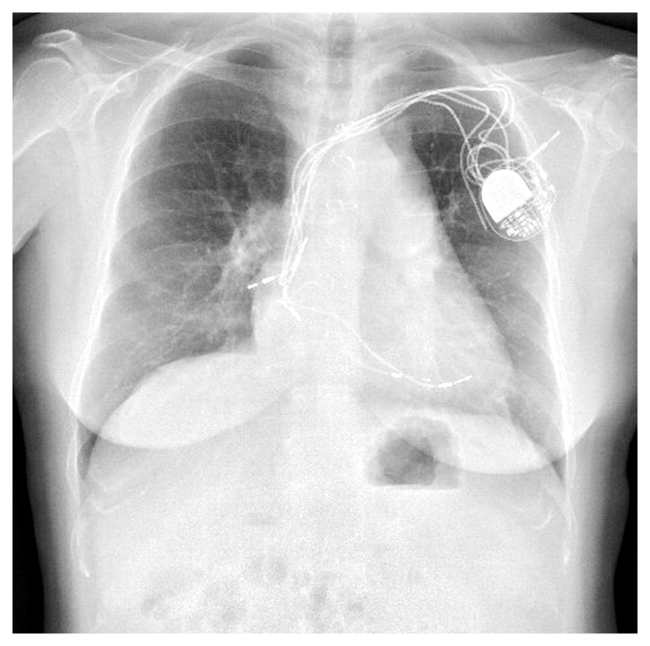
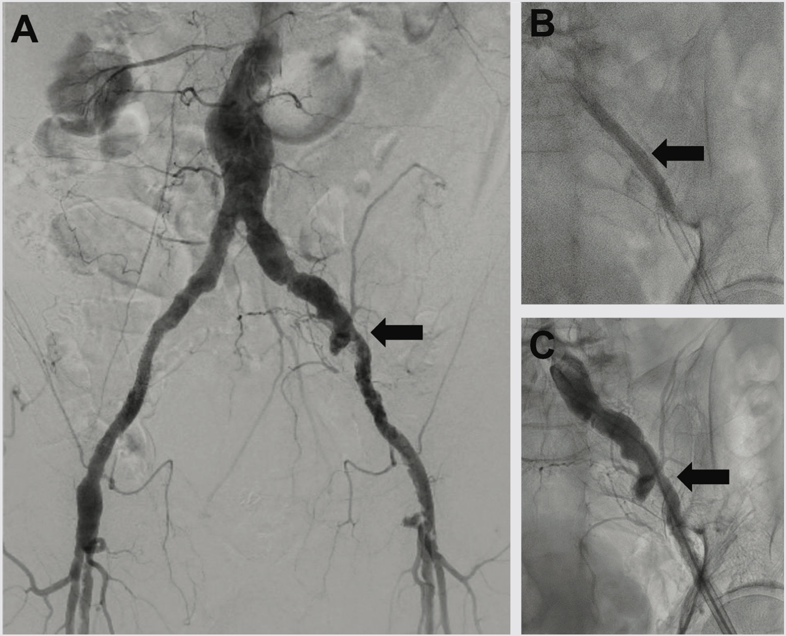
The pre-PCI right heart catherization showed a pulmonary capillary wedge pressure of 26 mmHg with a cardiac index of 2.0 L/min/m2. Because of marginal hemodynamics, we planned Impella (Abiomed)-supported PCI. Radial-to-peripheral iliofemoral angiography demonstrated (1) a patent right iliac stent and common femoral artery patch repair site, and (2) a severe calcific left iliac stenosis (Figure 2). To avoid access issues at the right femoral artery patch repair site, we opted for Impella implantation in the left common femoral artery (LCFA). The Impella sheath would not traverse the left iliac stenosis, so we treated with peripheral Shockwave balloon angioplasty (7.0 mm) (Shockwave Medical) to facilitate Impella placement and achieved an excellent angioplasty result (Figure 2).
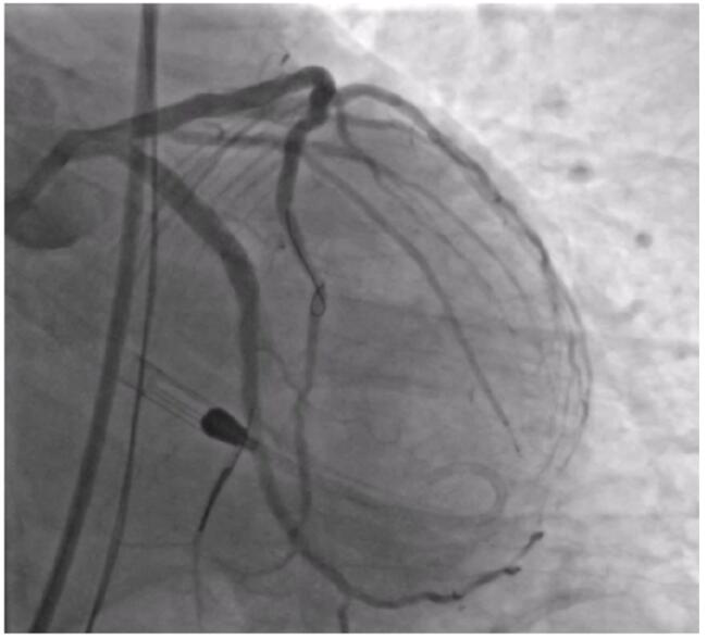
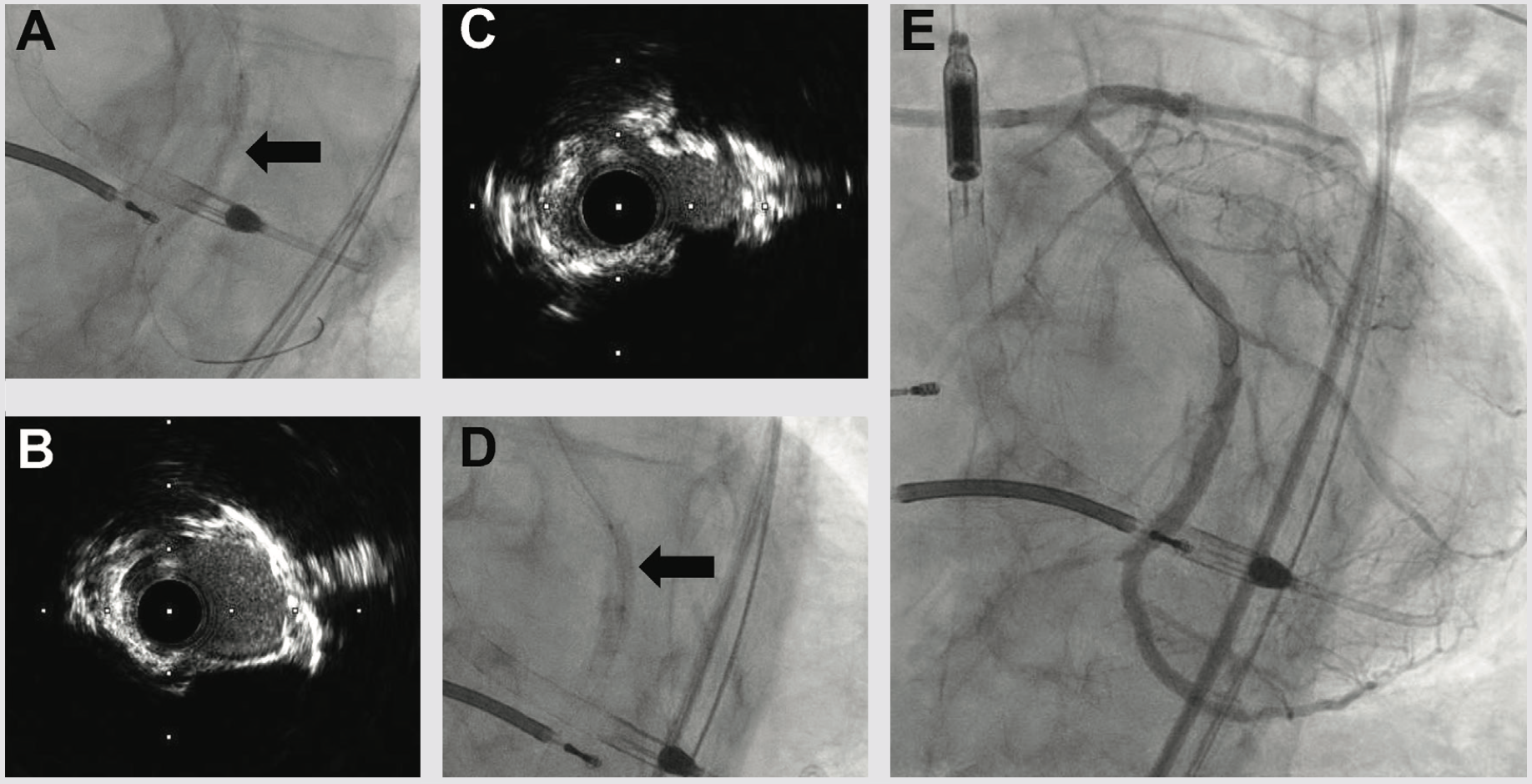
We next delivered the Impella CP and using single access guide technique (SHiP) through the Impella insertion sheath, placed a 7 French (Fr) left main guide, planning to treat the complex disease in the left circumflex. Diagnostic angiography demonstrated that the distal LCX to LPDA had progressed to a functional CTO. Using an antegrade wire escalation (AWE) strategy, we wired the LPDA with a Pilot 200 wire (Abbott Vascular), redirecting from a subintimal location to the artery true lumen. Predilation balloons would not expand, and intravascular ultrasound (IVUS) showed a severe arc of calcium and nodular calcium in the mid and distal LCX (Figure 3). With the assistance of a deep-seated guide extender, we treated with a 3.0 mm Shockwave balloon to modify the calcium compliance to facilitate optimal stent expansion (Figure 3). After Shockwave treatment, 1-to-1 sized AngioSculpt scoring balloons (Philips) expanded well, and we placed overlapping drug-eluting stents distal to the OM1 CTO into the LPDA. We next tackled the OM1 CTO with an AWE strategy. Using a Mongo wire (Asahi Intecc), we redirected from a subintimal location to the true lumen of the OM1. After 2.0 mm balloon inflation and nitroglycerine administration, the OM1 diameter was small, so we opted to stop at a balloon angioplasty result with non-flow limiting dissection, rather than placing a stent. We finally stented the proximal to mid left circumflex, IVUS optimized the stent expansion, and achieved an excellent IVUS and angiographic result (Figure 3). Having used 180 ccs of contrast to achieve the 2-vessel CTO AWE revascularization, we opted to stage the LAD CTO PCI procedure. We weaned the Impella in-lab, explanted the device, and the patient was discharged 3 days later at baseline renal function.
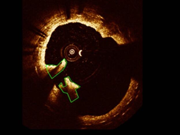
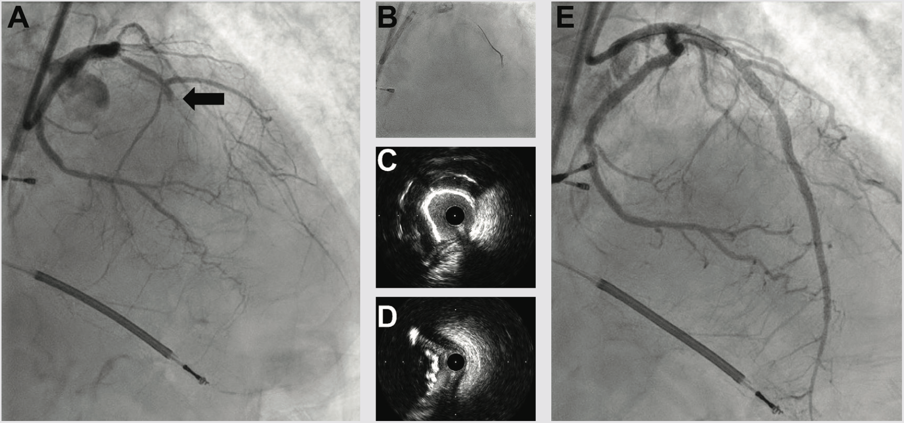
Three weeks later, we performed LAD CTO PCI. The LVEF had improved to 35%, and the patient was euvolemic and hemodynamically well compensated. Right radial occlusion and left radial vasospasm prevented 7 Fr radial access, so we re-accessed the LCFA, where angiography showed a widely patent iliac Shockwave treatment zone from the prior case. Using a 7 Fr system, diagnostic angiography demonstrated patency of the LCX, LPDA, and OM1 treatment sites. We next utilized an AWE strategy to address the LAD CTO (Figure 4). CTO wires immediately tracked subintimal and using a Mongo wire, we used mini-subintimal tracking and antegrade reentry (STAR) to reenter the LAD with <20 mm subintimal distance (Figure 4). Initial noncompliant balloons would not expand completely. IVUS showed (1) severe circumferential and nodular calcium in the proximal and mid LAD, and (2) limited (<20 mm) subintimal tracking before luminal reentry. We treated with a 3.5 mm Shockwave balloon to modify the calcium compliance to facilitate optimal stent expansion. After additional predilation with 1-to-1 sized noncompliant balloons, we placed overlapping stents, post dilated under IVUS guidance, and achieved excellent IVUS and angiographic results (Figure 4). The patient was discharged the following day, and on follow-up has had complete resolution of angina and no further heart failure exacerbations. Intravascular imaging identifies calcified stenoses that restrict stent expansion and reduce the durability of PCI revascularization. Shockwave intravascular lithotripsy improves the compliance of calcified stenoses to facilitate optimal expansion, with the goal of improving short- and long-term stent patency.
---
This article is sponsored by Shockwave Medical.
Dr. Croce is a paid consultant for Shockwave Medical.
See Important Safety Information below.
Learn more about coronary intravascular lithotripsy use by visiting Cath Lab Digest’s Calcium Corner.